Download the PDF document at the end of text.
This product is a miniCOB high-definition small-pitch LED electronic display produced by Shenzhen Only Optoelectronic Technology Co., Ltd. Its core advantages and applicable scenarios are as follows:
- Display Effect: High refresh rate, high grayscale, high brightness utilization rate, no image retention, capable of accurately reproducing the true colors of images, and no reflection in indoor applications.
- Physical Properties: Lightweight, ultra-thin design, high precision, occupying less transportation and usage space, facilitating installation and layout.
- Operation Advantages: Low power consumption, low electromagnetic interference (EMI), silent operation, high heat dissipation efficiency, strong stability, and long service life.
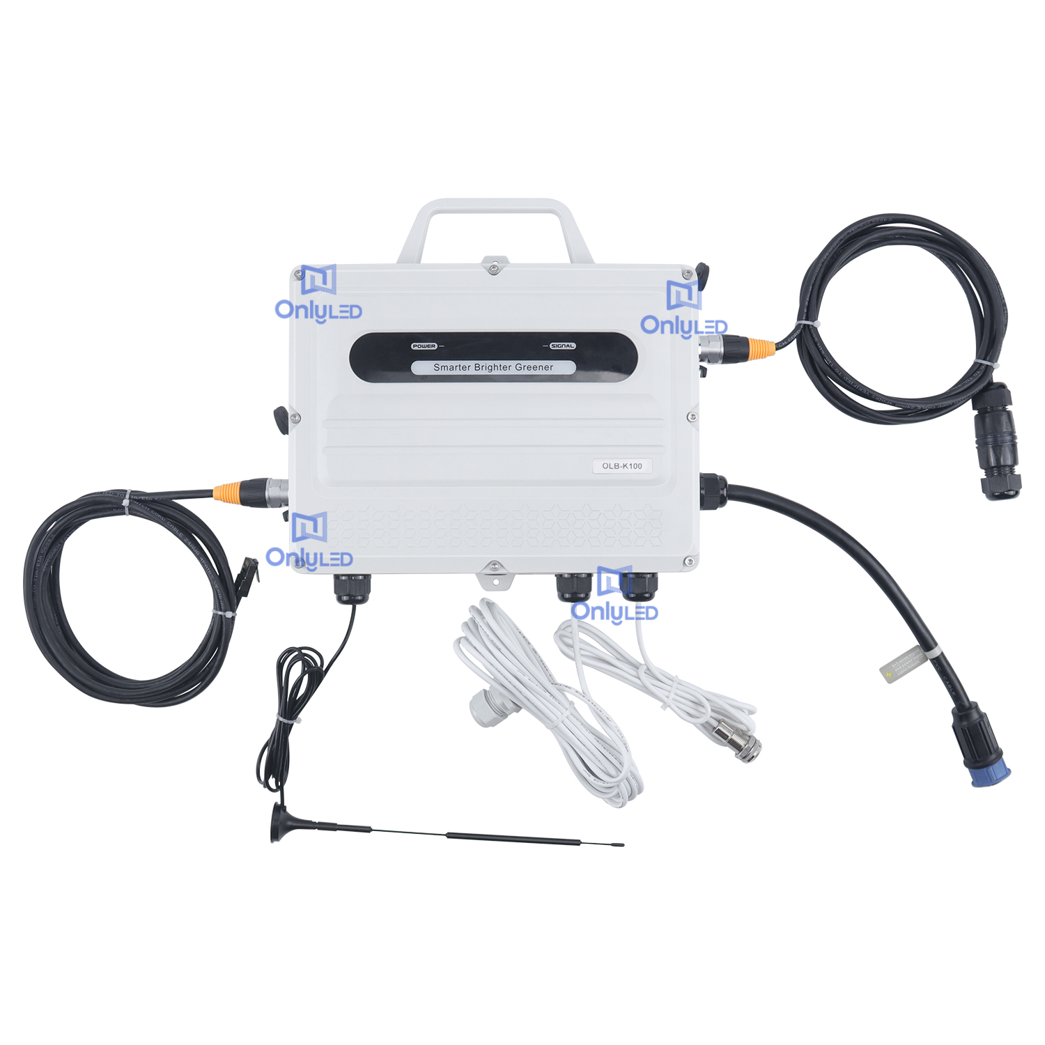
- Function Upgrade: Equipped with internationally advanced LED display-specific chip systems and full-color control systems, supporting advanced functions such as constant current noise reduction, common cathode energy saving, automatic brightness adjustment, and network cloud cluster control.
Widely used in indoor and outdoor intelligent advertising machines, stage performances, conference rooms, exhibitions, sports venues, hotel lobbies, etc. Among them, models such as P0.93, P1.25, P1.56, and P1.87 are representative of small-pitch displays. It is also suitable for professional fields such as commercial advertising, information dissemination, news releases, and securities trading.
- Cleanliness and Protection: Wear clean anti-static gloves during installation to avoid fingerprints on the surface of the light board; strictly prohibit paint, dust, welding slag, and other contaminants from adhering to the module light surface and display screen surface to prevent affecting the display effect.
- Environmental Restrictions: The product is not suitable for high-salt-fog, high-temperature, and high-humidity environments such as near the sea or water sources (which can easily cause components to be damp, oxidized, and corroded); if installation in a special environment is necessary, it is required to communicate with the manufacturer in advance, and the manufacturer will conduct customized treatment according to the special requirements of the on-site environment.
- Operation Specifications:
- Live operation is strictly prohibited (power must be cut off during installation, disassembly, and maintenance);
- Avoid the display screen coming into contact with water; use a damp towel to gently wipe the panel when cleaning;
- Do not place the LED light surface facing down on the floor, do not collide with the corners of the display screen, and do not drop the display screen;
- Some display screens are magnetic, so it is necessary to prevent metal objects from contacting the surface of the screen body.
- Product Protection: This product is a high-precision electronic product, so it should be handled with care during installation and disassembly to avoid damage caused by collision.
- Preparation: Carry out the splicing of cabinets on a flat and level tabletop. According to the cabinet numbering in the assembly schematic diagram, start from the bottom row and use edge lock screws to splice the cabinets one by one from left to right. Ensure that the cabinets are not misaligned and the numbers fully match the schematic diagram.
- Row-by-Row Assembly:
- After completing the splicing of the first row, assemble the second row and use edge lock screws to realize the double fixation of the cabinets in the vertical and horizontal directions;
- After assembling the second row, install internal connection pieces between the first row and the second row, and ensure that the cabinets are not misaligned at the same time.
- Fixation Process:
- Step 1: First, use edge lock screws to fix the adjacent cabinets up, down, left, and right;
- Step 2: Install the internal connection pieces of the cabinets;
- Step 3: Tighten the fixing screws of the connection pieces.
- Bulk Assembly: Follow steps 1-3 above to complete the assembly of all rows of cabinets in sequence.
Fix the assembled cabinet to the pre-prepared steel structure through "Structural Connection Piece A". During the installation process, ensure that the display screen body remains horizontal.
- Step 1: Determine the installation position of the display screen on the wall, and use an infrared level to calibrate the levelness of the bottom of the display screen;
- Step 2: Directly fix the assembled display screen body to the wall with drill-tail screws.
- Step 1: Determine the installation position of the display screen on the wall, and use an infrared level to calibrate the levelness of the bottom of the display screen;
- Step 2: Use L-shaped hooks and screws together, align the display screen body with the bottom horizontal line, and directly fix it to the wall.
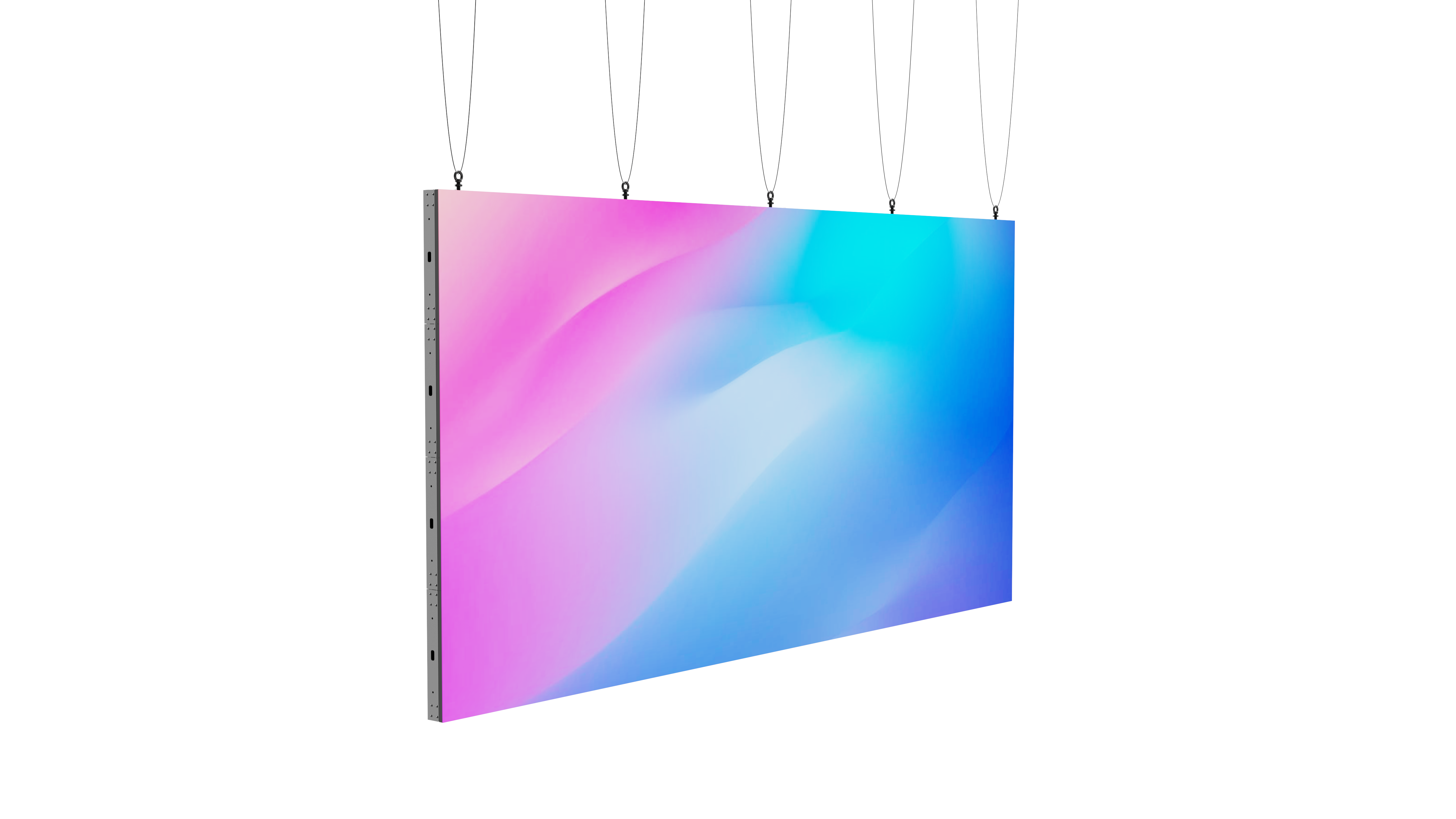
- Step 1: According to the size of the display screen and the preset installation position, install vertical hanger brackets at appropriate positions on the back of the cabinet;
- Step 2: Use an electric hammer to determine the hole positions on the wall and drill holes, then fix the hanging plate to the wall with expansion pipes and expansion screws (ensure the hanging plate is horizontal);
- Step 3: Install hooks on the back of the display screen;
- Step 4: Hang the display screen with fixed hooks on the wall bracket and tighten the safety screws;
- Note: The load-bearing capacity of the bracket is limited. For example, a 5×5 COB display screen is recommended to use two display brackets.
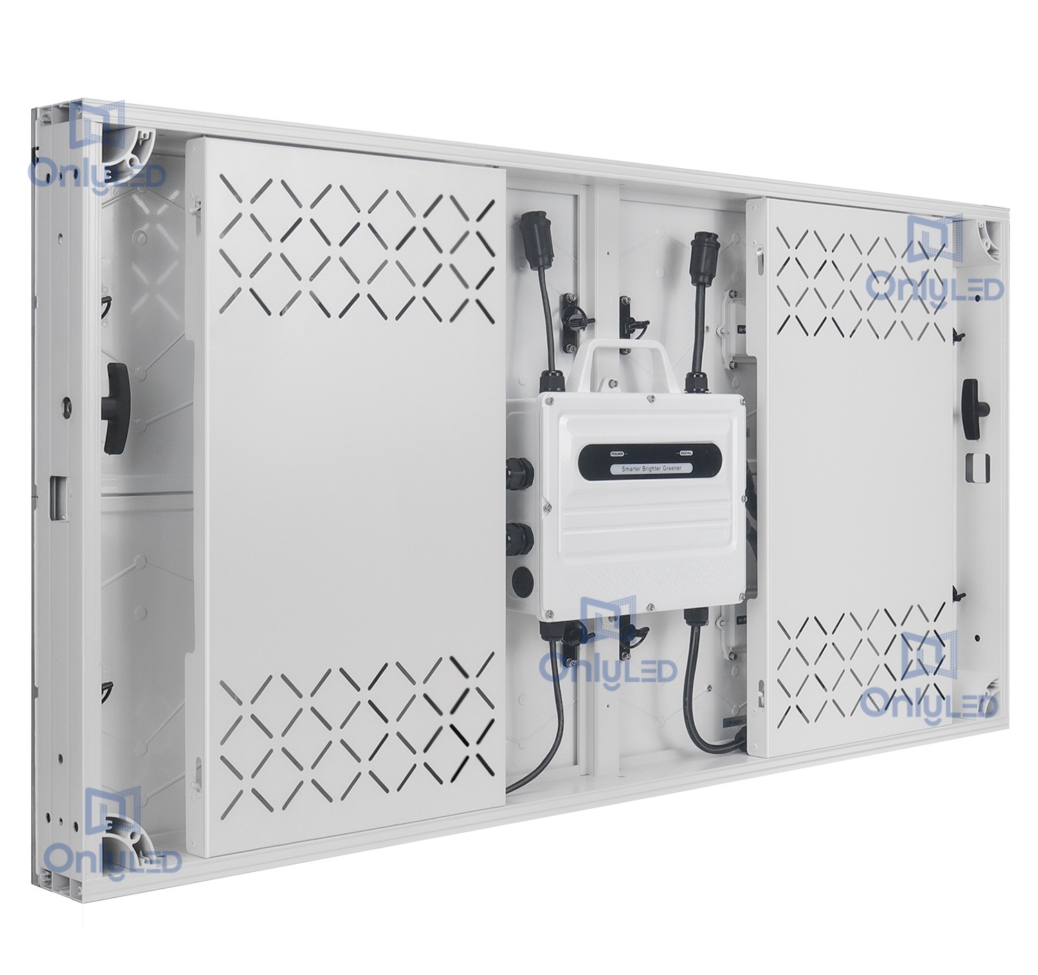
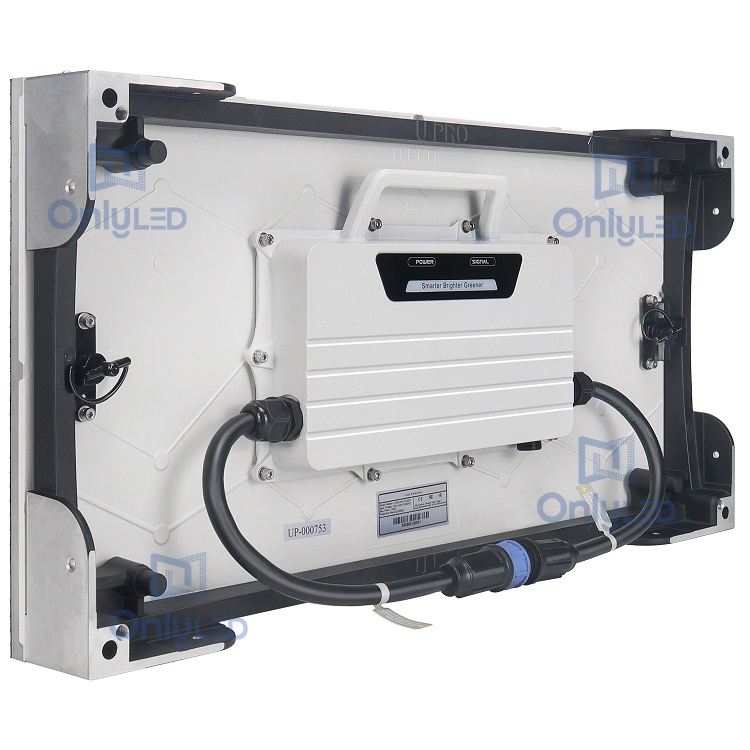
- After completing the cabinet structure installation, conduct the internal wiring of the cabinets according to the system wiring diagram. Carefully read the wiring diagram before wiring to avoid wrong connection.
- According to the requirements of the wiring diagram, pass the corresponding power cables and network cables through the wire holes between adjacent cabinets for connection; among them, the cabinet power cable is connected from the bottom of the screen body by default, the default length of the main power cable is 2 meters, and other lengths need to be customized in advance.
- After completing the internal wiring of the cabinets, connect the power inlet and the control system to ensure that the lines are connected firmly without looseness.
- Check whether the power cables of all cabinets are connected correctly. After confirming that there is no abnormality, power on for testing.
- Test Contents:
- Whether each cabinet is powered normally;
- Whether the receiver cards inside the cabinets work normally (normal state: the indicator light of the receiver card is always red, and the green light flashes once every second; if the indicator light state is abnormal, it needs to be checked and handled in time);
- Confirm that all receiver cards can be detected normally, and cut off the power after there is no abnormality.
- Before installation, confirm that the arrows on the cabinet and HUB board are upward, and the modules should be installed with the "arrows upward" direction.
- Number Correspondence: According to the module numbers in the cabinet light board installation diagram (for example, "A-1-1": the first letter "A" represents the first row, the second number "1" represents the first column, and the third number "1" represents the first light board in the first row and first column), find the corresponding modules for installation, and wrong installation is strictly prohibited.
- Installation Requirements:
- Ensure that there is no misalignment between modules. If there is slight misalignment, make timely fine adjustments to ensure the display effect;
- Maintain the flatness of the screen surface during the installation process;
- Wear gloves during operation to avoid contaminating the module surface and protect the smoothness of the cabinet surface.
- Finishing Cleaning: After the module installation is completed, use a dust-free cloth to wipe off the dust and fingerprints on the module surface.
- After completing all installation steps, power on for debugging to confirm that the display screen displays normally without abnormal problems.
- After the debugging is passed, it can be put into normal use.
- Before maintenance: Identify the modules to be disassembled/assembled, mark them, and then cut off the power.
- Disassembly Tool: Use a suction cup tool to absorb the module from the front of the screen body and pull it out gently to disassemble.
- First, turn off the power supply of the display screen to ensure that the power is completely cut off.
- Use a suction cup tool to disassemble the module from the front of the screen body, and unplug the power input cable of the module.
- Use tools such as a screwdriver to unscrew the screws fixing the driver board, remove the old driver board and replace it with a new one, and restore it according to the reverse steps after replacement.
 600x337.5 COB screen installation manual.pdf